01The problem问题
Pilot cells at 4.2 mAh/cm² delivered 77.4 % of their capacity at 2C, against 93.1 % for the current design and a requirement of 88 % for hill-climbing performance. The coating team had budgeted 14 coating trials to find a fix by iteration. Their standard model, which used the Bruggeman relation for tortuosity, predicted a much smaller loss, so it could not guide the search.
4.2 mAh/cm² 的中试电芯在 2C 下只能放出 77.4 % 的容量,而现有设计为 93.1 %,爬坡工况的要求是 88 %。涂布团队原计划通过 14 次涂布试验反复摸索。他们的常规模型用 Bruggeman 关系估算曲折度,预测的损失远小于实测,因此无法指导设计。
02What we did我们做了什么
Measure the real microstructure实测真实微观结构
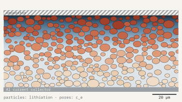
X-ray CT of the 4.2 mAh/cm² cathode at 0.4 µm voxels, segmented into particles, carbon-binder and pore. The through-plane tortuosity factor computed directly from the pore network was 4.1, against 2.9 from Bruggeman. That gap explained why the standard model under-predicted the loss.
对 4.2 mAh/cm² 正极做 0.4 µm 体素的 X 射线 CT,并分割出颗粒、导电剂-粘结剂与孔隙三相。从孔隙网络直接算得的厚度方向曲折度因子为 4.1,而 Bruggeman 估算值为 2.9——这正是常规模型低估损失的原因。
Validate the cell model first先验证电芯模型
A homogenised P2D model using the measured tortuosity reproduced the pilot cells' rate test to within 2 points of capacity at 2C.
采用实测曲折度的均质化 P2D 模型复现了中试电芯的倍率测试,2C 容量误差在 2 个百分点以内。
Explore the design space遍历设计空间
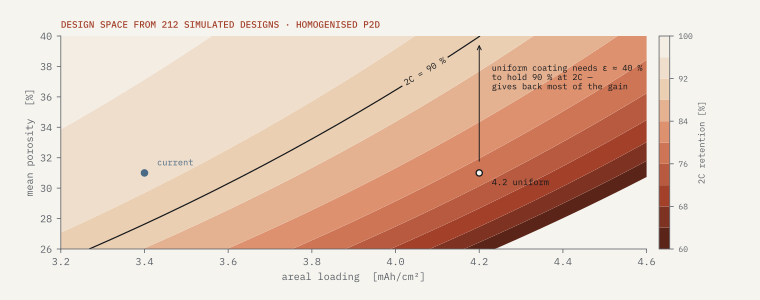
212 simulated designs varying loading, mean porosity, conductive-additive content and two-layer grading.
仿真 212 个设计方案,变量包括面容量、平均孔隙率、导电剂含量与双层梯度。
Confirm with targeted trials定向试验确认
Five coating trials, down from the 14 planned, built only the top-ranked designs on the client's slot-die line.
在客户的狭缝涂布线上,只对排名靠前的设计做了 5 次涂布试验(原计划 14 次)。
03Results结果
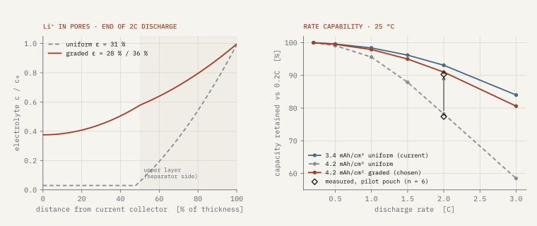
- Chosen design: a two-layer cathode at 4.2 mAh/cm², 28 % porosity at the current collector and 36 % on the separator side.
- 最终方案:4.2 mAh/cm² 双层正极,集流体侧孔隙率 28 %,隔膜侧 36 %。
- 2C retention 90.3 % measured (model 91.0 %), against 77.4 % for the uniform thick electrode.
- 2C 容量保持率实测 90.3 %(模型 91.0 %),均匀厚电极为 77.4 %。
- +8.5 % Wh/L and +7.2 % Wh/kg at cell level. Client cycling to 500 cycles shows no difference from the current design.
- 电芯体积能量密度 +8.5 %,质量能量密度 +7.2 %。客户循环至 500 次,与现有设计无差异。
04Limits of validity适用边界
NMC622 cathodes at 3.2–4.6 mAh/cm² and 26–40 % porosity, 25 °C, discharge up to 3C. Fast charging and low-temperature performance of the thick design were not part of this study.
适用于 NMC622 正极,面容量 3.2–4.6 mAh/cm²,孔隙率 26–40 %,25 °C,放电倍率不超过 3C。厚电极设计的快充与低温性能不在本次研究范围内。